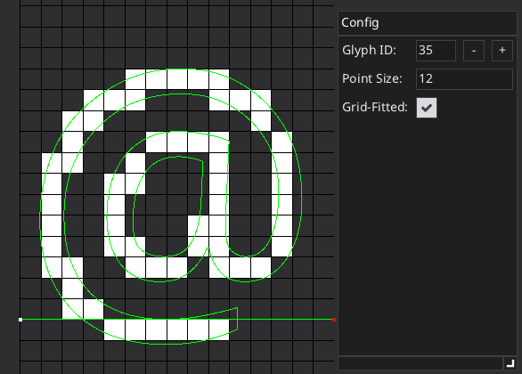
Disclaimer: I have not implemented all instructions yet because they are not used by the font I’m testing (Noto Sans Regular). More notes might appear here once I find the need/time to implement them. I’ve been using FontForge’s debugger to check my implementation (CVT values, stack state, calculated values, etc.).
Initialization
- Load
head table to get unitsPerEM
- Load
maxp table to get number of glyphs in the font + additional maximum values for working data (e.g. max twilight points, max storage, max function defs, etc.)
- Load
hhea table to get font global metrics (ascent, descent, linegap, etc.)
- Load
hmtx table to get advance widths and left side bearings of all glyphs
- Load
loca table to get offsets of glyph data in glyf table.
- Load
glyf table
- Load
cvt table
- Load
fpgm table
- Load
prep table
- Initialize the virtual machine
- Allocate
maxp.maxFunctionDefs function definitions
- Allocate a
maxp.maxStackElements stack and reset it
- Allocate 2 CVT arrays (size calculated from the size of the
cvt table)
- 1 for current CVT values
- 1 for initial CVT values
- Allocate
maxp.maxStorage storage array.
- Initialize Zone 0 with a capacity of
maxp.maxTwilightPoints
- Initialize Zone 1 with a capacity of
maxp.maxCompositePoints
- Set point size and display DPI to
0
- Execute
fpgm program
Runtime
- If current point size or display DPI is different than previous values.
- Transform
cvt table values from FUnits to 26.6 into current CVT array.
- Initialize graphics state to default values
- Reset zone 0 points to 0
- Execute the
prep program
- Copy current graphics state to initial graphics state
- Copy current control values to initial CVT array.
- 2024-05-29: Copy current storage values to initial storage array.
- Copy initial graphics state to current graphics state
- Copy initial CVT array to current CVT array
Reset storage array to 0 (2024-05-29: Copy initial storage array to current storage array.)- Reset zone 0 point flags to 0 (all points untouched). Coordinates should not be reset!
- Transform glyph points from FUnits to 26.6 format and mark all points as untouched, into zone 1
- Add 4 phantom points to zone 1
- (0, 0)
- (glyph’s advance width, 0)
- (0, ascent)
- (0, descent)
- Execute the
glyf program
Notes
- According to the specs, function and instruction definitions cannot be nested. That means that when executing the
fpgm or prep programs and an FDEF[] instruction is encountered, searching for the next ENDF[] instruction is enough to find the boundaries of the function. The only thing to keep in mind is instructions pulling data from the instruction stream (NPUSHB[], NPUSHW[], PUSHB[n] and PUSHW[n]). If such instruction is encountered during the search for ENDF[], you have to skip their data bytes before continuing to the next instruction.
MUL[] and DIV[] instructions should round the intermediate 52.12 result before converting back to 26.6 (i.e. (x+63)/64; at least this is what FontForge seems to be doing).FLOOR[] and CEIL[] should handle negative 26.6 numbers correctly (i.e. for x < 0, floor(x) = -ceil(-x)).- Zones hold both the initial (transformed from FUnits to the current point size and display DPI) positions of each point and their final/grid-fitted positions. They also hold 2 flags/bits for each point indicating whether the X or Y coordinate has been touched by a previous instruction. Some instructions operate on either one of those 2 sets of coordinates (e.g. indicated by the instruction opcode, like
GC[a]). All instructions not specifying what set of coords should be used will have to check the touched flags and use the corresponding set (if touched, use the grid-fitted coords, otherwise use the initial coords).
- FontForge seems to round the 4 phantom points in the grid-fitted array. I.e. if advance width of a glyph ends up being 17.6px, the initial 2nd phantom point is set to (17.6, 0) and the corresponding grid-fitted phantom point is rounded to (18, 0).
- FontForge seems to copy the initial (transformed) coords of each point to the grid-fitted array when the program starts. This avoids any checks of the touched flags when executing instructions which do not explicitely specify which set of coords should be used.
- There is an issue with twilight zone points and their initial positions (afaict they don’t have any by definition). What I decided to do is, everytime an untouched twilight point is touched, I copy the just-calculated grid-fitted coordinate to the initial array. This way e.g.
MD[1] can be calculated correctly for such points.
- Even though projection and freedom vectors are in 2.14 format, in order to perform any calculations with 26.6 numbers I decided to convert them to 26.6 instead of writing proper 26.6/2.14 operations. This isn’t a problem with the font I’m testing because both vectors seem to always be axis aligned (i.e. (0.0, 1.0)) so there is no loss in precision. Might have to rethink it if I encounter a font which sets them to arbitrary values (via
SPVTL[a], SFVTL[a], etc.).
IUP[a] operates on all untouched points between 2 sequentially touched points. E.g in a sequence p1, p2, p3, p4, p5, if only p1 and p4 have been touched, both p2 and p3 should be interpolated using p1 and p4 as reference points. Tbh, I don’t know if there should be any change to p5 (I don’t currently move p5).- I’m using a
scalerVersion of 35 (Microsoft Rasterizer 1.7) which matches the one used by FontForge (see GETINFO[]). This requires 4 phantom points. Versions less than that require only the first 2 (horizontal) phantom points.